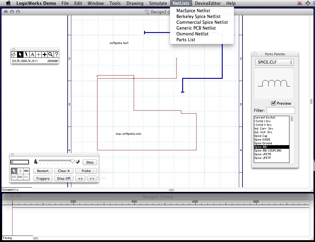

Click the right mouse button to drop the device. Do the same for two-input OR gates OR-2 and inverters that is denoted NOT gate in the library. You can rearrange the gate positions by picking one up and dragging it with the left mouse button. You can copy a gate by choosing it and choosing Edit->Copy (Control-C) and then Pasting it. 2.4 Connecting gates To connect two pins with a wire, select the end of one pin with left mouse button and pressing and dragging the cursor to the end of the other pin. The wire can be placed piece by piece at right Jianjian Song LogicWorks 4 Tutorials (5/5/3) of 4ģ angles by dragging and releasing the wire. A replaced wire can be rerouted by selecting and dragging it in any direction. 2.5 Labeling inputs and output signals and pins Click on the text icon (button with letter A) in the Tool Palette. Use the pencil to pick a wire to be named by clicking on the wire. If your pencil is close to a pin, you may pick a pin instead of a wire. You can number the pin by giving it a pin number. Pin numbers can be seen by right clicking on a device and choosing Device Info->Pin Info.

By default, pin numbers are in blue and signal names are in pink. Type a name for the wire and then press the enter key. The name can be dragged to another location while still associated with the same wire.Ī signal name can be changed by double clicking on it and then making a change. Conflict will occur if two wires have the same name.

Label all the signals as shown in the given circuit. 2.6 Connecting binary switches to input pins Select Simulation IO.clf in the device library palette. Connect one binary switch to one input signal of the circuit.


 0 kommentar(er)
